- Name – Compact Pipe
Technical description of a rehabilitation method
tight-fit liner compact pipe
according to PN-EN 752-2; 752-5, 13689; ISO 11296-1; ISO 11296-4.
1. Material
Compact Pipe tight-fit lining rehabilitation method uses polyethylene pipes of factory-reduced cross-section pipe. Depending on local conditions, the pipes can be made of PE80 or PE100 and can have different SDR for specific diameters.
2. Liner installation equipment
- cleaning equipment (pressure truck, scrapers)
- remotely controlled inspection camera
- remotely controlled milling machine
- pipe welding unit (butt-welders and resistance welders)
- guide rollers
- pulling machine (pipe puller)
- steam generator
- by-passing unit (pumps, hoses)
- expander (for calibrating liner diameter)
- testing equipment
3. Preparation to installation
Before starting the rehabilitation process, it is necessary (if required) to construct special by-passes ensuring continuity of supply. Once a pipeline section is isolated, it is cleaned and inspected using a remotely controlled camera. The video (or DVD) footage is used for preparing a detailed digital report on the pipeline’s technical condition.
4. Installation
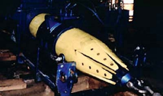
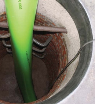
A towline is pulled into the pipeline. To the end of the towline a guiding head is connected (using a swivel shackle). It is connected (through a thermally-connected PE-HD plate) to Compact Pipe. Once the whole liner section is unwound from the transport drum and pulled in, the liner is cut and the end is secured by butt-welding a temporary plate that makes it possible to connect the process head.
Steam and compressed air hoses are connected to the head. When the liner is equipped with temperature and pressure sensor and a steam / condensate separator is installed at the end, the proper installation process begins.
Compact Pipe liner is heated with steam until it reaches the required temperature then compressed air is supplied. It inflates the pipe and tightly presses it to the walls of the existing pipeline which causes cooling of the plasticized Compact Pipe liner.
When the installation process is complete, the guide head and the temporary plate are cut-off. Bare ends of Compact Pipe liner are calibrated using a hydraulic expander equipped with strengthening sleeves and connected using a resistance sleeve with appropriate adaptor or another section of Compact Pipe liner.
5. Inspection
5.1. TV Inspection
After the installation and opening connections, acceptance TV inspection (including VHS or CD recording) is carried out. Inspection report is also prepared.
5.2. Tests
According to PN-EN ISO 11296-1, 11296-4.
6. Correction of flaws
Flaws are corrected using a robot controlled via a camera or / and inserting and gluing short pipe sections.
- Name – Compact Slimliner
Technical description of a rehabilitation method
tight-fit liner compact slimliner according to PN-EN 752-2; 752-5, 13689; 13566-1; 13566-3.
1. Material
In the tight-fit Compact Slimliner water piping rehabilitation method we use thin-walled polyethylene pipes with factory-reduced cross-section. Compact Slimliner is an interactive liner using the rehabilitated pipeline as a structural element.
2. Liner installation equipment
- cleaning equipment (pressure truck, scrapers)
- remotely controlled inspection camera
- remotely controlled milling machine
- guide rollers
- pulling machine (pipe puller)
- by-passing unit (pumps, hoses)
- expander (for calibrating liner diameter)
- testing equipment
3. Preparation to installation
Before starting the rehabilitation process, it is necessary (if required) to construct special by-passes ensuring continuity of supply. Once a pipeline section is isolated, it is cleaned and inspected using a remotely controlled camera. The video (or DVD) footage is used for preparing a detailed digital report on the pipeline’s technical condition.
4. Installation
A towline is pulled into the pipeline. Compact Slimliner is connected (through a swivel shackle) to the end of the line. Once the whole liner section is unwound from the transport drum and pulled in, the liner is cut and the end is secured by installing a special temporary fitting needed for connecting a water hose.
The hose supplying cold water under required pressure is connected to the liner. After the time stated in the instructions for use, water supply is cut, distorted ends are cut even, and the liner is installed and secured in the old pipeline. The old pipeline functions as a structural element for Compact Slimliner.
5. Inspection
5.1. TV Inspection
After the installation and opening connections, acceptance TV inspection (including VHS or CD recording) is carried out. Inspection report is also prepared.
5.2. Tests
According to PN-EN 13566-1, 13566-3.
6. Correction of flaws
Flaws are corrected using a robot controlled via a camera or / and inserting and gluing short pipe sections.
- Name – Omega Liner
Technical description of a rehabilitation method
Tight-fit liner omega liner
according to PN-EN 752-2; 752-5; 13689; 13566-1; 13566-3.
1. Material
In the tight-fit Omega Liner sewer rehabilitation method we use modified polyvinyl chloride pipes with factory-reduced cross-section. Due to its design and parameters, Omega Liner is used only for rehabilitation of non-pressure networks. Circumferential rigidity of the liner (SN 4 to SN 8) is selected on the basis of relevant static strength calculations.
2. Installation equipment
- cleaning equipment (pressure truck)
- remotely controlled inspection camera
- remotely controlled milling machine
- guide rollers
- pipe-sauna (for pre-heating the liner before installation)
- pulling machine (pipe puller)
- steam generator
- by-passing unit (pumps, hoses)
- testing equipment
3. Preparation to installation
Assessment of the sewer’s technical condition
Before starting rehabilitation, the pipeline is cleaned using a hydrodynamic sewer cleaning unit mounted on a truck. Then the pipeline is inspected using a remotely controlled camera. The video footage is used for preparing a detailed digital report on the pipeline’s technical condition. The data provides the base for classifying the sewer’s technical condition.
Choice of the rehabilitation method
The rehabilitation method depends on the technical condition class and damage degree. After the assessment of the sewer’s technical condition, geodetic data have to be analyzed, including ground water level compared to the base of the sewer, motor traffic in the area, and other parameters that impact parameters of the selected liner. Based on that and the Young modulus (E) characterizing the proposed material, the designer determines the wall thickness and diameter of tight-fit Omega Liner.
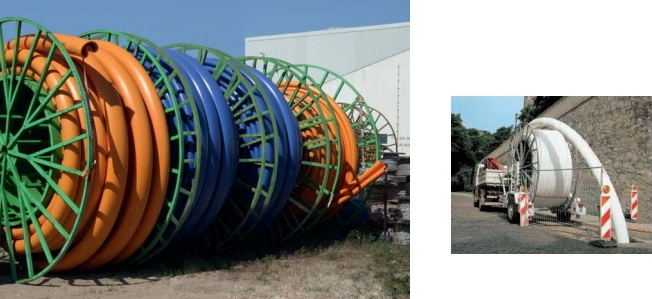
Storage and transport to the site
The liner is coiled on a drum with dimensions 3.0 x 3.0 x 1.6 m and is delivered using regular transport means to the construction site’s storage location. Drums are stored vertically on a paved storage yard. The liner is transported to the construction site in a pipe sauna to prevent cooling down.
4. Installation
To install the liner in the rehabilitated sewer, it has to be plugged above the section to be rehabilitated. In case of high inflow, a pump or a set of pumps for by-passing the section has to be installed upstream the rehabilitated section.
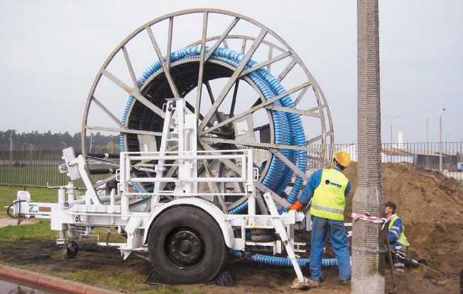
Then, Omega Liner, pre-heated in the sauna, is introduced to the cleaned and prepared sewer using a pulling machine with adjustable and recordable pulling strength.
When the liner is in the pipeline, special-design steam plugs are installed in the insertion and terminal manholes. Then the liner is evenly heated to about 65oC using steam with temperature up to 90oC. When it is evenly heated, the liner has to be inflated using compressed air under the pressure of 0.8 – 1.0 bar. Afterwards, the liner is cooled using cold air to about 30oC. Once cooled, the steam plugs are cut off and TV inspection is carried out.
All the “acute-connected” house drains are opened using a milling robot.
During the installation the following process parameters have to be recorded: temperature of the pre-heated liner, pulling strength, and all the temperature readings from all the control points during proper heating process.
5. Inspection
5.1. TV Inspection
After the installation and opening connections, acceptance TV inspection (including VHS or CD recording) is carried out. Inspection report is also prepared.
5.2. Tests
According to PN-EN 13566-1, 13566-3 and PN-EN 1610
6. Correction of flaws
Flaws are corrected using a robot controlled via a camera or / and inserting and gluing short pipe sections..
- Name - Swagelining
Technical description of a rehabilitation method
Tight-fit liner swagelining
according to PN-EN 752-2; 752-5; 13689; 13566-1; 13566-3.
1. Material
In the tight-fit SWAGELINING pipeline rehabilitation method we use polyethylene pipes of the cross-section reduced at the site. Due to safety of installation, we use pipes made of PE100.
2. Liner installation equipment
- cleaning equipment (pressure truck, scrapers)
- remotely controlled inspection camera
- remotely controlled milling machine
- pipe welding unit (butt-welders and resistance welders)
- guide rollers
- swaging unit
- pulling machine (pipe puller)
- by-passing unit (pumps, hoses)
- testing equipment
3. Preparation to installation
Before starting the rehabilitation process, it is necessary (if required) to construct special by-passes ensuring continuity of supply. Once a pipeline section is isolated, it is cleaned and inspected using a remotely controlled camera. The video (or DVD) footage is used for preparing a detailed digital report on the pipeline’s technical condition.
4. Installation
The first stage is to prepare a sufficiently long PE pipe section for the installation (by welding a required number of sections together) and placing the liner on installation rollers.
The SWAGELINING rehabilitation method consists in temporary swaging of the pipe by reducing its diameter, causing its elongation. The process is to make it possible to introduce the prepared section into the old pipeline.
The pulling force is controlled all the time in the process to protect PE against overstretching. When the pipe swaged in phase 1 of the installation process is in place, the load applied to the section is released by disconnecting the pulling machine. Internal tension forces cause the pipe to return to its original size. The PE pipe expands and abuts against the walls of the rehabilitated pipeline ensuring so-called tight-fit.
5. Inspection
5.1. TV Inspection
After the installation and opening connections, acceptance TV inspection (including VHS or CD recording) is carried out. Inspection report is also prepared.
5.2. Tests
According to PN-EN 13566-1, 13566-3.
6. Correction of flaws
Flaws are corrected using a robot controlled via a camera or / and inserting and gluing short pipe sections.